Hello my fellow hackers! Today we’re going to be introducing a topic we should’ve covered long ago, networking. Having an understanding of networking gives us a better understanding of how computers interact with each other. If we understand how these systems communicate over the network, we can better manipulate parts of the network to our advantage. Things such as routers and switches allow us to reach other parts of the network, and learning to manipulate such devices could allow for greater access to the network as a whole. The first couple of articles in this series will be all about the basics. We’ll start here with the OSI model, and work our way up. Once we’ve covered the OSI model, we’ll begin to discuss different network protocols in depth, exploring what they do, and how to exploit them. So, without further adieu, let’s talk about the OSI model!
The OSI Model
The OSI model is a model that breaks down network communication into seven layers. Each layer represents another set of functionalities that are used to get data from point A to point B.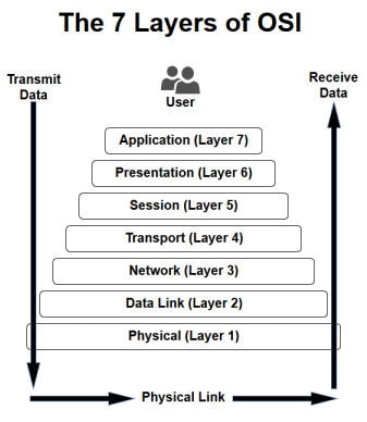 The act of data moving up and down the layers of the OSI model is known as encapsulation and decapsulation. Data being encapsulated moves down the OSI model, while data being decapsulated moves up the OSI model. This representation makes the most sense when analysed from the bottom up, so that what we’ll do.
Layer 1 (Physical Layer)
Layer 1, the physical layer, is very simple. The physical layer is the actual media that the data moves across. Whether it be fiber optics or standard ethernet, the physical layer is the physical media on which our data is moving. For an example of a layer 1 networking device, we’ll take a look at a long out-dated piece of networking technology, the hub.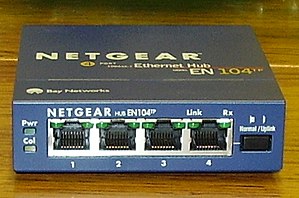 A hub is a very old device that was originally meant to create small LANs. It works by listening for the electric pulses coming into any port, and replicates those electrical pulses out all other ports, effectively passing the data. Since it replicates all pulses out all other ports, this is considered a layer 1 device.
A hub is a very old device that was originally meant to create small LANs. It works by listening for the electric pulses coming into any port, and replicates those electrical pulses out all other ports, effectively passing the data. Since it replicates all pulses out all other ports, this is considered a layer 1 device.Layer 2 (Data Link Layer)
Since layer 1 is the physical media, it’s easy to think of layer 2 as a sort of point to point connection. A single node on a network connects to another node, fragmenting, transmitting, and reassembling data as it is passed through the physical layer.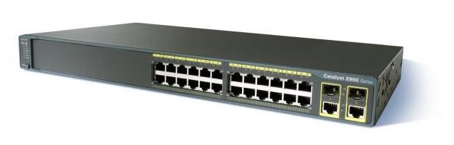 The above networking device is a switch. It is primarily used to provide access to the network for the hosts. A switch may serve the same basic functions as a hub, but it’s much smarter in the way it goes about it. Instead of replicating data out all ports, switches send data to the port they are destined for. Imagine it like this: if our NIC connecting to the switch port is layer 2, then the switch can look at all the “point to point” connections it has to decide where data should go. This is what classifies the switch as a layer 2 device.
The above networking device is a switch. It is primarily used to provide access to the network for the hosts. A switch may serve the same basic functions as a hub, but it’s much smarter in the way it goes about it. Instead of replicating data out all ports, switches send data to the port they are destined for. Imagine it like this: if our NIC connecting to the switch port is layer 2, then the switch can look at all the “point to point” connections it has to decide where data should go. This is what classifies the switch as a layer 2 device.Layer 3 (Network Layer)
So, if our layer 2 is a set of point to point connections, our layer 3 can be thought of as the functionality that allows us to send data to and from these groups of connections.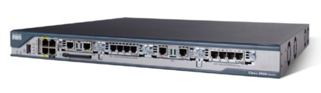 The above device is a router, which is used for routing information between networks. Here at layer 3, IP addresses are used to identify nodes on a network (at layer 2, a MAC or burnt-in address is used). Since IP can be used to represent a node on a network, routers generally have more than 1 IP address and reside on more than 1 network. This allows them to pass data between networks, such as a home network and an ISP network.
The above device is a router, which is used for routing information between networks. Here at layer 3, IP addresses are used to identify nodes on a network (at layer 2, a MAC or burnt-in address is used). Since IP can be used to represent a node on a network, routers generally have more than 1 IP address and reside on more than 1 network. This allows them to pass data between networks, such as a home network and an ISP network.Layer 4 (Transport Layer)
Layer 4 and above gets slightly different than the other layers. Yes, there are devices that operate at layer 4, such as some stateful firewalls, but most of the layer 4 functionality relies on the TCP/IP stack which is installed on all systems that access the network. The transport layer is in charge of just that, transport. There are two main protocols that live at layer 4, TCP and UDP. At this layer port numbers are used to mark where to send data to. A port in this instance is a logical interface on a computer that can either create or receive connections. For example, the SSH service runs on port22.
Layers 5 and 6 (Session and Presentation Layers)
Layers 5 is responsible for controlling connections between systems. Not only does it start them, but it also manages and terminates them. The presentation layer on the other hand is used to convert data back and forth between being machine readable and human readable.
Layer 7 (Application Layer)
Layer 7 is the final layer of our OSI model. The application layer is just that, the application that the data being encapsulated/decapsulated serves. Whether it be DHCP, HTTP, or FTP, the data within is considered application layer data.
That does it for this one! Next time we’ll be focusing more on the layers’ roles in a network, rather than their definitions. Also, we’ll be reviewing another model in the near future, the TCP/IP model. By the end of this series we should be able to look around a network and identify what the infrastructure looks like.


0 comments:
Post a Comment